Arduino UNO
The Arduino Uno is a popular microcontroller board based on the ATmega328P microcontroller. It is widely used for building electronic projects due to its simplicity, versatility, and ease of use.
Features and Components of the Arduino Uno
-
Microcontroller: ATmega328P.
-
Operating Voltage: 5V.
-
Digital I/O Pins: 14 (of which 6 can provide PWM output).
-
Analog Input Pins: 6.
-
Flash Memory: 32 KB (ATmega328P) of which 0.5 KB used by the bootloader.
-
SRAM: 2 KB (ATmega328P).
-
EEPROM: 1 KB (ATmega328P).
-
Clock Speed: 16 MHz.
-
USB Connection: Used for power and programming.
-
Power Jack: For external power supply.
-
Reset Button: To reset the microcontroller.
Arduino Uno Pinout and details
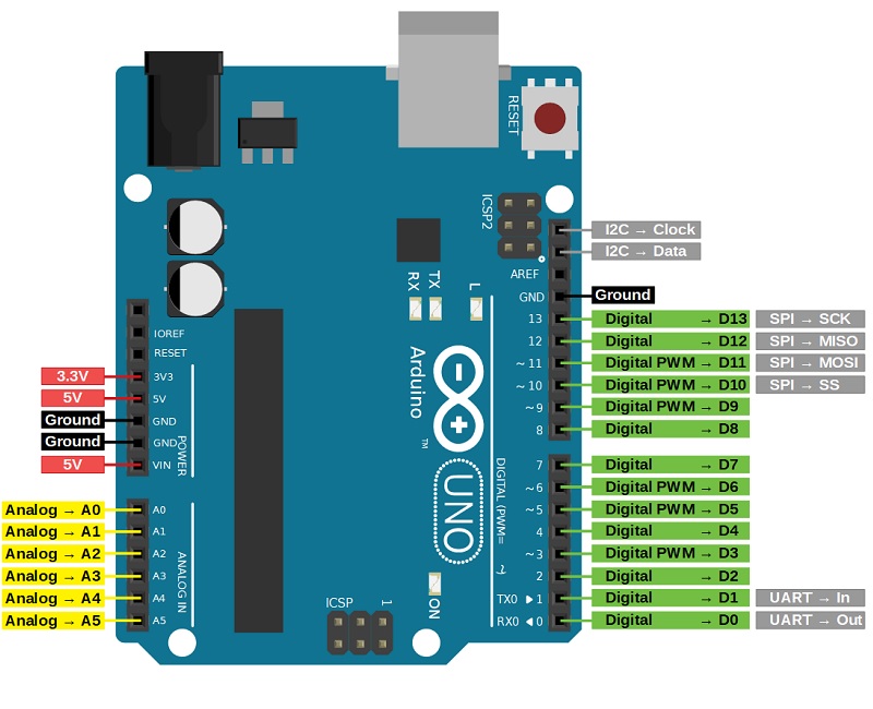
Power
-
Vin: Input voltage to the Arduino board when using an external power source (7-12V).
-
GND: Ground pins.
-
5V: Provides a stable 5V output from the board’s voltage regulator, useful for powering external components and devices.
-
3.3V: A 3.3V supply generated by the on-board regulator. Maximum current draw is 50 mA.
-
Reset: When the Reset Pin is connected to ground (GND), it resets the microcontroller.
Analog In
Analog pins (A0-A5) are used for reading analog signals from sensors and other input devices.
-
Voltage Range: Typically 0 to 5V.
-
Resolution: 10-bit Analog-to-Digital Converter (ADC), which provides values from 0 to 1023.
-
Usage: Commonly used to interface with analog sensors like temperature sensors, light sensors, potentiometers, etc.
Digital I/O Pins
Digital pins (0-13) are used for both input and output operations involving binary signals (high and low states). These pins are essential for interfacing with digital devices and components, such as LEDs, buttons, and communication modules.
-
Function: Read and write digital signals (HIGH or LOW).
-
Voltage Levels:
-
HIGH: 5V
-
LOW: 0V
-
-
PWM (Pulse Width Modulation): 3, 5, 6, 9, 10, and 11 pins can simulate analog output by rapidly switching between HIGH and LOW states with varying duty cycles. It used for LED dimming, motor speed control, and audio signal generation.
Communication Pins
The Arduino Uno has several pins dedicated to communication, allowing it to interface with other devices, sensors, and microcontrollers. These communication protocols include Serial (UART), SPI, and I2C.
-
Serial (UART) Communication: Tx (1) and Rx (0) Used for serial communication. Where Rx (Pin 0) use for receive data and Tx (Pin 1) use for transmit data.
-
SPI (Serial Peripheral Interface) Communication: Purpose of use it for high-speed synchronous data transfer between the Arduino and peripherals such as sensors, SD cards, and shift registers.
-
SS (Pin 10): Slave Select. Used to select the SPI device.
-
MOSI (Pin 11): Master Out Slave In. Used to send data from the master to the slave.
-
MISO (Pin 12): Master In Slave Out. Used to receive data from the slave to the master.
-
SCK (Pin 13): Serial Clock. Used to synchronize data transfer between master and slave.
-
-
I2C (Inter-Integrated Circuit) Communication: Allows multiple devices to share the same communication bus using unique addresses. Commonly used for sensors, displays, RTC modules, and other peripherals.
-
SDA (A4): Serial Data. Used for data transfer between master and slave.
-
SCL (A5): Serial Clock. Used to synchronize data transfer.
-
AREF Pin
The AREF pin is used to set a custom reference voltage for the ADC (Analog-to-Digital Converter), enhancing the accuracy and flexibility of analog input readings. By providing a stable and appropriate reference voltage.
IOREF Pin
The IOREF (Input/Output Reference) pin is a reference voltage indicator that helps ensure compatibility between the board and external shields and modules. By providing a standard reference voltage (typically 5V for Arduino Uno), it allows shields to automatically adjust their logic voltage levels, enhancing interoperability and ease of use in Arduino-based projects.