LCD 16x2 Module
The 16x2 LCD module is a popular component in many electronics projects, especially for displaying information in a readable format. This module has 16 columns and 2 rows, allowing to display up to 32 characters at a time.
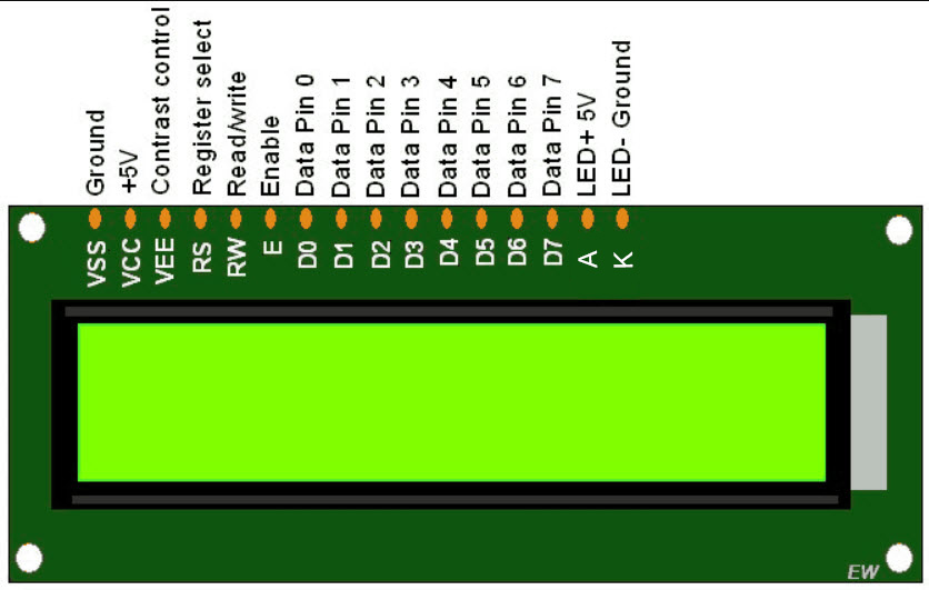
LCD 16x2 Pinout and details
-
VSS (Pin 1)
-
Function: Ground pin
-
Connection: Connect to the ground (GND) of the circuit.
-
-
VDD (Pin 2)
-
Function: Power supply pin
-
Connection: Connect to +5V power supply.
-
-
VO (Pin 3)
-
Function: Contrast adjustment
-
Connection: Connect to the middle pin of a 10k potentiometer. The other two pins of the potentiometer go to +5V and GND.
-
-
RS (Pin 4)
-
Function: Register Select
-
0: Command register (for instructions)
-
1: Data register (for data)
-
-
Connection: Connect to a microcontroller I/O pin.
-
-
RW (Pin 5)
-
Function: Read/Write
-
0: Write operation
-
1: Read operation
-
-
Connection: Connect to GND (for write operations).
-
-
E (Pin 6)
-
Function: Enable pin
-
When high, it reads data from the bus.
-
When low, data is written to the bus.
-
-
Connection: Connect to a microcontroller I/O pin.
-
-
D0-D7 (Pins 7-14)
-
Function: Data pins
-
D0-D7 (Pins 7-14): 8-bit data bus.
-
D4-D7 (Pins 11-14): Commonly used in 4-bit mode.
-
-
Connection: Connect to microcontroller I/O pins.
-
-
A (Pin 15)
-
Function: LED (+) (Anode for backlight)
-
Connection: Connect to +5V through a current-limiting resistor.
-
-
K (Pin 16)
-
Function: LED (-) (Cathode for backlight)
-
Connection: Connect to GND.
-